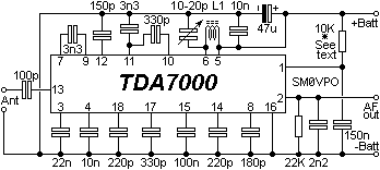
Circuit Diagram of theFM Reciever
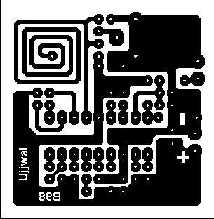
PCB Layout of the FM Reciever
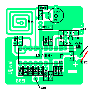
Component Layout of the FM Reciever
| VHF FM RECEIVER |
| There has been a lot of interest in the TDA7000 receiver following the posting of my VFH FM Wireless Microphone. This circuit is a perfect companian for the FM transmitter projects , thus I am also giving the proposed PCB layout for the project. Coil winding for this project is not needed because I have fabricated the tuning coil on the PCB. This should also give a better stability. The PCB size is 45mm x 46mm (TA7000b). |
Circuit Diagram of theFM Reciever |
| This receiver has a sensitivity (inserted MUTE resistor) of 1.5uV which is 20 times more sensitive than a standard commercial VHF FM receiver. This receiver should realise the full range of my VHF FM wireless microphone. This receiver incorporates "AFC" which has an effective range of 300KHz. The AF output level is in the order of 80-100mV so an external amplifier is required. |
PCB Layout of the FM Reciever |
Component Layout of the FM Reciever |
| Capacitors *1 sets the maximum frequency to which the receiver may be tuned to and *2 sets the total frequency range of the receiver. The tuning capacitor "VC" should be 15pf. |